UNIVERSAL CENTERLESS GRINDING |
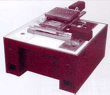
| The Curtis UCG (Universal Centerless Grinder) is a
revolutionary concept for centerless grinding machines. The grinding wheel is mounted on CNC controlled X / Z slides so that it can be moved between grinding and dressing positions. This allows the grinding wheel to be dressed at the front of the wheel - thus eliminating the taper variations normally experienced when dressing at the rear of the wheel and allows all types of dressing devices to be freely interchanged to give a truly universal machine. The UCG slideway arrangement allows all the required movements to be made with only 3 linear slides (6 are normally required for conventional centerless machines). |
| The UCG base and X / Z slides are the same as used on the well proven Curtis D150 high precision external grinding machine. The machine base is of an advanced design with a mineral composite fill to give high damping. The infeed and traverse slides use very stiff linear slideways and high precision ball screws directly coupled to digital servomotors. Linear scale feedback for high precision positioning 0.0001 is available as an option. |
|
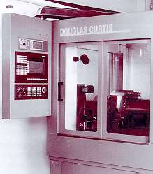 |
The UCG is fitted with a Siemens
840 control system. This has great flexibility due to its modular construction with a MMC
CPU at its core which is PC compatible allowing for easy transfer of programmes. The 250mm
LC colour flat screen is mounted in a pivoting console enabling the operator to view from
either operating area. Siemens 611AC servo drives are used with digital AC servomotors.
Customised software with interactive operator screens enable easy machine settings. The machine is fully enclosed and complies with relevant standards. Separate access is provided to the dressing and grinding areas and the control pendant can be swivelled so that the machine can be opened through either of the access points. The guarding is designed so a range of automatic loading systems can be mounted in the most suitable way so access is not restricted. |
Special Features |
|
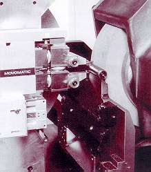
| In-cycle Component
Measuring A standard twin finger-measuring unit is mounted adjacent to the grinding wheel and a slot or slots are made in the work rest so that the component can be measured across its diameter. After grinding the wheelhead is moved to the guaging position and the gauge head advanced pneumatically. The machine control is updated to correct for size variations. A complete gauging cycle takes approximately 5 seconds. |
|
| Acoustic Gap Control /
Crash Control Acoustic gap control can be fitted to minimise 'fresh air grinding' thus reducing cycle times. When dressing this enables precise contact to be made between tool and the grinding wheel. Crash control reduces damage to the machine in the event of a collision. Automatic loading |
Grinding Wheel Sizes & Speeds With no dressing device built into the wheel guard, the wheel size can be selected to suit the application. The standard wheel size is 350mm diameter x 150mm wide with the option of 450mm diameter with widths up to 100mm. The UCG set-up allows for the full utilisation of the latest grinding wheel technology and cutting speeds. Changing the Grinding Wheel |
Application Details |
|
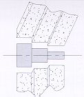
Angle Approach Centerless GrindingThe grinding spindle can be set at an angle to the component axis. Combined movement of the machine's X / Z slides facilitates angle approach grinding allowing diameters and shoulders to be ground at the same time.
|
 |
Multi-plunge grindingFor high precision applications two grinding wheels can be mounted to
allow rough and finish grinding in the same cycle.
|
 |
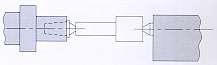
Between Centre Grinding on a Centerless Grinding Machine!The unique design of the control wheel spindle allows either a centre or chuck to be mounted. The addition of a tailstock allows between centre grinding. This is not intended to compete with dedicated external grinding machines, but is ideal for jobbing shops.
|
 |
Quick Set-upFor ease of setting, the grinding wheel can be moved clear of the
grinding area, allowing the workrest blade to be set, and 'clocked' from the Z-axis to
give very accurate setting. On Machine Dressing of Diamond and CBN wheelsFor precision grinding of hard materials using Diamond and CBN wheels it is imperative that the wheel runs true to the spindle axis. On the UCG these wheels can be dressed on the machine both for straight and formed wheels.
|
|
Dressing Options |
Grinding Wheel DressingThe grinding wheel dressing units are mounted on a large, fixed platform with the grinding wheel moved to the dressing position automatically by the main X / Z slides. There are six optional dressing units, which can be interchanged quickly by the machine operator. |
|
Control Wheel DressingThe control wheel is dressed from the main X / Z slides. A diamond-dressing arm is automatically pivoted from the grinding wheel head and dresses the control wheel at the same height as the component contact point on the control wheel. The control wheel is dressed under CNC control and no tooling is required, only PCD diamond inserts. High Thermal StabilityConventional centerless grinding machines dress the grinding and control wheels at the rear. As a result any thermal movement within the grinding wheel head results in taper variations in the component. The UCG overcomes this problem by dressing the grinding and control wheels at the front from the main CNC slides. Integral Automatic Grinding Wheel BalancingThe grinding wheel balancer is mounted inside the spindle directly under the wheel. The signals to the balancer are taken through the spindle to the pulley end where non-contact connections are made. The balancer is sealed into the spindle. |

|
QUOTATIONS AND ENQUIRIES If you need a
quotation or want to make a general enquiry, please click on the
enquiry form button below and complete the simple form that follows. |
